https://support.xilinx.com/s/article/1058302?language=en_US
TITLE
AXI Basics 3 - Master AXI4-Lite simulation with the AXI VIP
AUTHOR
florentw
LAST PUBLISHED DATE
10/12/2021, 8:46 AM
BODY
Introduction
In the previous AXI Basics articles, we have been through a brief description of the AXI4 specification (AXI Basics 1) and we had an introduction to the AXI Verification IP (AXI VIP) (AXI Basics 2).
In this new entry we will see how we can add an AXI VIP into a Vivado project to simulate an AXI4-Lite interface. We will then look at the signals used for AXI4-Lite transactions in the simulation waveform window.
Using the AXI VIP as an AXI4-Lite Master (tutorial)
-
Download the design files attached to this article
-
Open Vivado 2019.2
-
In the Tcl console, cd into the unzipped directory (cd AXI_Basics_3)
-
In the Tcl console, source the script tcl (source ./create_proj.tcl)
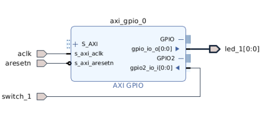
This will create a Vivado project with a Block Design including an AXI GPIO IP. This AXI GPIO IP has one output connected on its channel 1 simulating a connection to on-board LED that we will try to turn ON/OFF with AXI4-Lite transactions and one input connected on its channel 2 simulating a connection to the on-board switch that we will try to read the state of.
5. Add an AXI Verification IP (AXI VIP) to the design.
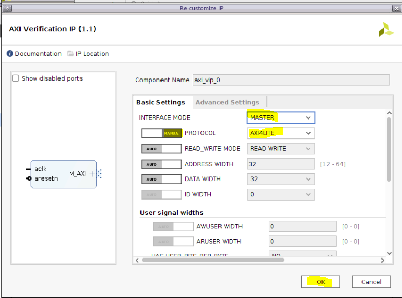
- Double-click on the AXI VIP to open its configuration GUI and change the following parameters:
- Interface mode : MASTER
- Protocol (MANUAL): AXI4LITE
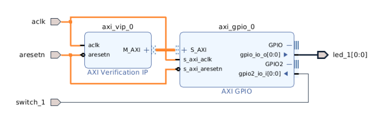
7. Connect the Master AXI4-Lite interface of the AXI VIP (M_AXI) to the slave AXI4-Lite of the AXI GPIO IP (S_AXI) and the aclk and aresetn ports of the AXI VIP to the inputs of the Block Design
8. Open the Address Editor tab (Window > Address Editor) and click on the Auto Assign address icon
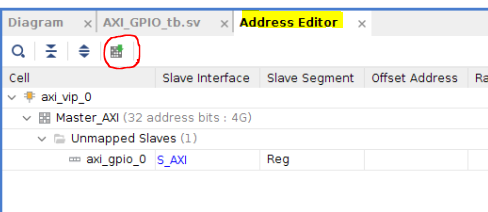
9. Make sure that the address set is 0x4000_0000
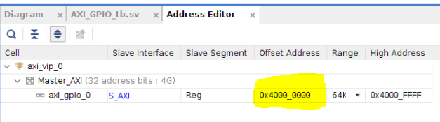
10.Note*: The upper part of the address does not really matter here, because if you check the S_AXI interface of the AXI GPIO, only 9 address bits are connected to the AXI VIP
- Validate the block design. You should have no errors or critical warnings.
Save the block design.
Now we need to update the test bench file to declare and control the AXI VIP.
To do so, we will follow the Useful Coding Guidelines and Examples from PG267 (v1.1, October 30, 2019) p46.
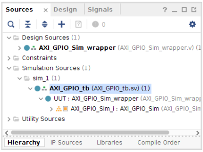
- Open the test bench file, AXI_GPIO_tb.sv from the Sources window
The test bench file already includes the control of some signals (for example the clock and the reset) and has processes to output the status of the LEDs to the console
always @(posedge led_1) begin $display(“led 1 ON”); end always @(negedge led_1) begin $display(“led 1 OFF”); end
The first step mentioned in the Useful Coding Guidelines and Examples is to create a module in the SystemVerilog test bench. This is already done in the test bench.
The second step is to import two required packages: axi_vip_pkg and <component_name>_pkg.
13.Note*: to find the <component_name> for the VIP instance, use the following Tcl command and find the output corresponding to the AXI VIP instance.
The attached test bench assumes that the AXI component name is design_1_axi_vip_0_0 (the default for the first AXI VIP added to a BD)
get_ips vip
- Add the following lines around line 58
//Step 2 - Import two required packages: axi_vip_pkg and <component_name>_pkg. import axi_vip_pkg::; import AXI_GPIO_Sim_axi_vip_0_0_pkg::;
Step 3 is to declare an agent of type master VIP
- Add the following lines around line 102
// Step 3 - Declare the agent for the master VIP AXI_GPIO_Sim_axi_vip_0_0_mst_t master_agent;
Steps 4 and 5 consist of creating a new agent and starting it.
- Add the following lines around line 107
// Step 4 - Create a new agent master_agent = new(“master vip agent”,UUT.AXI_GPIO_Sim_i.axi_vip_0.inst.IF); // Step 5 - Start the agent master_agent.start_master();
Everything is now ready to start sending the transactions.
Sending an AXI4-Lite transaction is really easy. We just have to use the APIs AXI4LITE_WRITE_BURST(addr,prot,data,resp) for a write transaction and AXI4LITE_READ_BURST(addr,prot,data,resp) for a read transaction.
17.Note*: All of the APIs for the AXI VIP are documented in a zip file which you can download from Xilinx.com here.
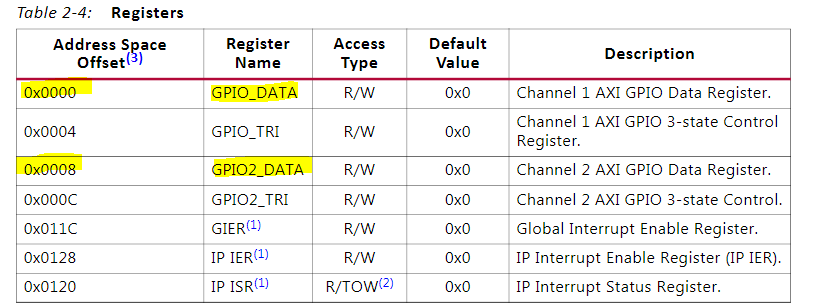
In this tutorial, we will try to toggle the LED_1, which is connected to the AXI GPIO Channel 1, and read the state of SWITCH_1, which is connected to the AXI GPIO Channel 2.
Looking at the register map for the AXI GPIO IP, per Table 2-4 from (PG144), we have to write at addresses 0x0 and read at address 0x8:
We will start with the write, trying to toggle the state of the LED_1.
18. Add the the following code to write 0x1 to the AXI GPIO register 0x0, which should turn ON the LED
//Send 0x1 to the AXI GPIO Data register 1 #500ns addr = 0; data = 1; master_agent.AXI4LITE_WRITE_BURST(base_addr + addr,0,data,resp);
- Add the the following code to write 0x0 to the AXI GPIO register 0x0, which should turn OFF the LED
//Send 0x0 to the AXI GPIO Data register 1 #200ns addr = 0; data = 0; master_agent.AXI4LITE_WRITE_BURST(base_addr + addr,0,data,resp);
Next we will do a read after each change of position of the switch and display the state of the switch to the console.
20. Add the following code corresponding the the read transaction:
// Switch in OFF position switch_1 = 0; // Read the AXI GPIO Data register 2 #200ns addr = 8; master_agent.AXI4LITE_READ_BURST(base_addr + addr,0,data,resp); switch_state = data&1’h1; if(switch_state == 0) $display(“switch 1 OFF”); else $display(“switch 1 ON”); // Switch in ON position switch_1 = 1; // Read the AXI GPIO Data register 2 #200ns addr = 8; master_agent.AXI4LITE_READ_BURST(base_addr + addr,0,data,resp); switch_state = data&1’h1; if(switch_state == 0) $display(“switch 1 OFF”); else $display(“switch 1 ON”);
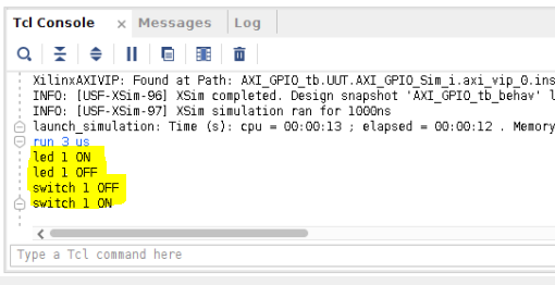
- Launch the simulation and run it for 3us. In the Tcl console, you should see that the LED is toggling and that we are getting the state of the switch
We can now analyze the transactions on the AXI4-Lite interface
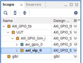
- In the scope window, select the axi_vip_0 under AXI_GPIO_tb > UUT > AXI_GPIO_Sim_i
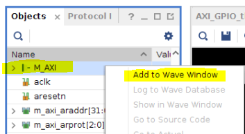
23. In the object window, right-click on the M_AXI protocol instance and click Add to Wave Window
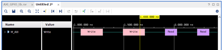
24. Restart the simulation and re-run it for 3us
We can see the 4 transactions on the AXI4-Lite interface: 2 write transactions followed by 2 read transactions
25. Expand the M_AXI protocol instance to see the different channels
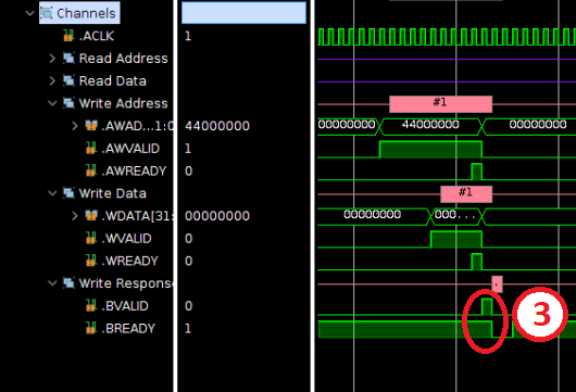
We can then see the different steps for a write transaction.
First, the address is transmitted from master to slave when both the READY and VALID signals are high on the write address channel (AWREADY and AWVALID)

Then the data is transmitted from master to slave when both the READY and VALID signals are high on the write channel (WREADY and WVALID).
26.Note*: Only one piece of data per address will be transmitted as bursts are not supported on AXI4-Lite interfaces.
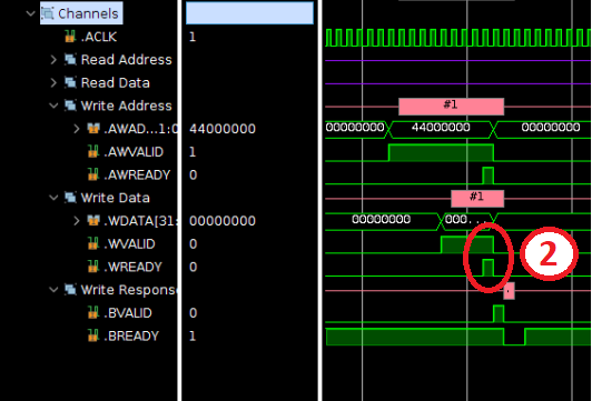
Finally the write transaction completes when the slave sends the write response (to tell if the write was successful) on the write response channel. The response is transmitted from slave to master when both the READY and VALID signals are high on the write response channel (BREADY and BVALID)
We can do the same analysis for the Read transaction.
First the data is transmitted from master to slave when both the READY and VALID signals are high on the read address channel (ARREADY and ARVALID)
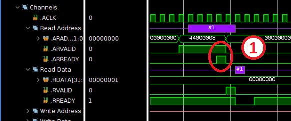
Then the data is transmitted from slave to master when both the READY and VALID signals are high on the read channel (RREADY and RVALID).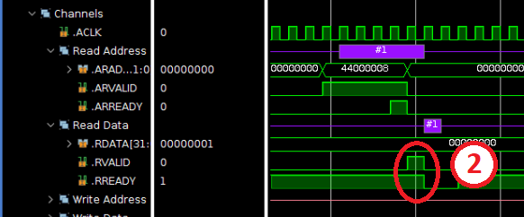 Note: During read transactions, the slave will also send a response to indicate if the read was successful.This response will be sent at the same time as the data on the read channel.
Additional Learning
If you want to learn more about AXI, please see the other tutorials in this series: