https://support.xilinx.com/s/article/1064306?language=en_US
TITLE
AXI Basics 5 - Create an AXI4-Lite Sniffer IP to use in Xilinx Vivado IP Integrator
AUTHOR
florentw
LAST PUBLISHED DATE
10/12/2021, 10:23 AM
BODY
Introduction
In some cases, it might be useful to sniff an AXI interface to analyze the transactions which are happening on it. In this article I will show you how to create a basic AXI4-Lite sniffer IP which will count the read/write transactions happening at a specific address.
We will start by writing the HDL (Verilog) code, then package the code as an IP and finally we will add this IP to an IP Integrator Block Design (BD).
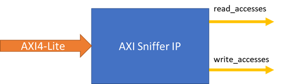
The AXI Sniffer we will create will have an AXI4-Lite input interface to sniff an AXI4-Lite link and two outputs to give the number of Read and Write transactions which happened at a specific address (which will can configured through the GUI).
Create an AXI Sniffer IP to use in Vivado IP Integrator (tutorial)
-
Download the design files attached to this article
-
Open Vivado 2019.2
-
In the Tcl console, cd into the unzipped directory (cd AXI_Basics_5)
-
In the Tcl console, source the script tcl (source ./create_proj.tcl)
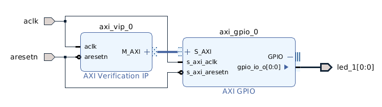
This will create a Vivado project with a BD including an AXI VIP set as AXI4-Lite master and an AXI GPIO IP. This is very similar to the final design we made in the AXI Basics 3 article.
In this project, we will create the AXI Sniffer IP then try to connect it to the AXI4-Lite interface between the AXI VIP and the AXI GPIO IPs
We can start by writing the HDL (Verilog) code for our AXI Sniffer IP
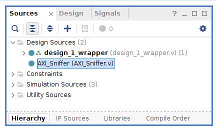
5. Double-click on the AXI_Sniffer.v file in the Sources window to open the file in the text editor
We first need to declare the ports of the IP. We need an AXI4-Lite interface. As per the AMBA® AXI™ and ACE™ Protocol Specification available from the ARM website (link)), these are the signals required on an AXI4-Lite interface

We also need to add the 2 ports (read_accesses and write_accesses) which will output the count of read/write accesses to the address the IP will be watching.
6. Add the following code to declare all of the required signals.
module AXI_Sniffer ( input aclk, input aresetn, input s_axi_arvalid, input s_axi_arready, input [31:0] s_axi_araddr, input [2:0] s_axi_arprot, input s_axi_rvalid, input s_axi_rready, input [31:0] s_axi_rdata, input [1:0] s_axi_rresp, input s_axi_awvalid, input s_axi_awready, input [31:0] s_axi_awaddr, input [2:0] s_axi_awprot, input s_axi_wvalid, input s_axi_wready, input [31:0] s_axi_wdata, input [3:0] s_axi_wstrb, input s_axi_bready, input s_axi_bvalid, input [1:0] s_axi_bresp, output [31:0] read_accesses, output [31:0] write_accesses );
7.Note*: All of the AXI4-Lite signals are set as input in this case because the IP should not act on the AXI4-Lite interface, only monitor the traffic on it
Then, our IP needs to have a parameter to set the address which we want to monitor
- Add the following code to add the parameter for the monitoring address
module AXI_Sniffer #( parameter SLAVE_BASE_ADDR = 32’h40000000 ) (
Finally, we need to add the logic which will count the number of accesses to the address. The code increases a counter each time tready and tvalid are high while the address we are looking at is set.
- Add the following code to the file
10.reg [31:0] read_accesses_cnt; reg [31:0] write_accesses_cnt; assign read_accesses = read_accesses_cnt; assign write_accesses = write_accesses_cnt; //Check the Read Address Channel always @(posedge aclk) begin if(aresetn == 0) begin read_accesses_cnt = 0; end else if (s_axi_arready && s_axi_arvalid && s_axi_araddr == SLAVE_BASE_ADDR) begin read_accesses_cnt = read_accesses_cnt + 1; end else read_accesses_cnt = read_accesses_cnt; end //Check the Write Address Channel always @(posedge aclk) begin if(aresetn == 0) begin write_accesses_cnt = 0; end else if (s_axi_awready && s_axi_awvalid && s_axi_awaddr == SLAVE_BASE_ADDR) begin write_accesses_cnt = write_accesses_cnt + 1; end else write_accesses_cnt = write_accesses_cnt; end* endmodule
- Save the file AXI_Sniffer.v
In IP Integrator, there is a feature which allow the user to import a HDL file into a BD that we can try.
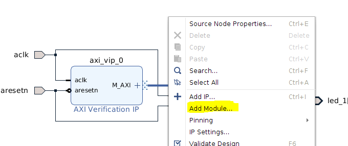
- Right-click on the BD and click Add Module…
 We can see that the tool correctly groups all of the s_axi_* signals to create an interface s_axi. However, if we try to connect this interface on the existing connection between the AXI VIP and the AXI GPIO, the tool will not allow us to.
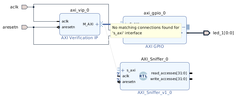
This is because the import module tool has set the s_axi interface as a slave and Vivado only allow a master interface to be connected to a single slave.
To create the monitor IP we need to package the code as an IP, which will give us more options for the interface.
-
Click on Tools > Create and Package New IP…
-
On the second page of Create and Package New IP, select Package a specified directory and click Next
-
Select the directory AXI_Basics_5/src/hdl/AXI_Sniffer then click Next > Next (keep default settings) > Finish
This will create an IP Packager project. In the Package IP tab, click on the Ports and Interface section.
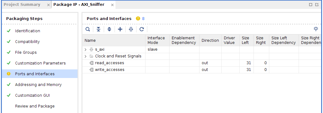
We can see that the tool has again grouped the s_axi_* signals into a s_axi interface. But this interface is still set as a Slave. To be able to connect to an existing AXI bus, we need to tell the tool that this is a not a slave interface but a monitor interface.
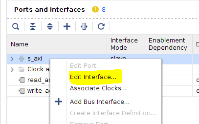
16. Right-click on the s_axi interface and click Edit Interface…
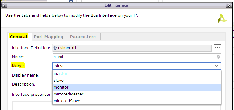
17. In the General tab of the Edit Interface window, change the Mode to monitor
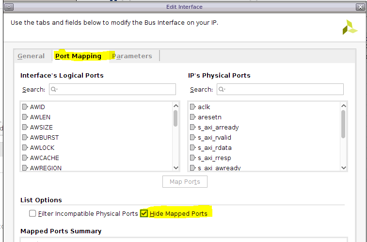
18. Then click on the Port Mapping tab and enable Hide Mapped Port
19. For each IP’s Physical Ports named s_axi_*, find the matching Interface’s Logical Ports and click Map Ports
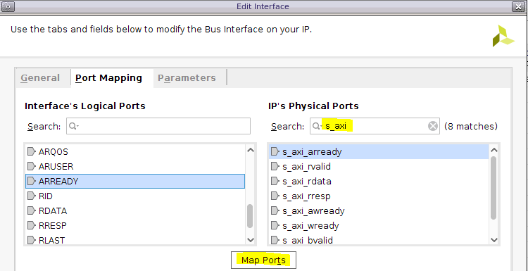
20. When all of the s_axi_* IPs ports are mapped click OK to close the Edit Interface window
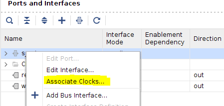
- Right-click again on the s_axi interface and click Associate Clocks…
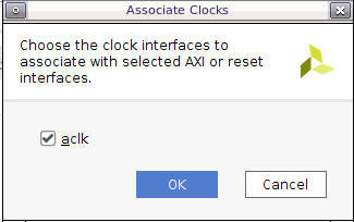
22. In the next window, aclk should be automatically selected. Click OK
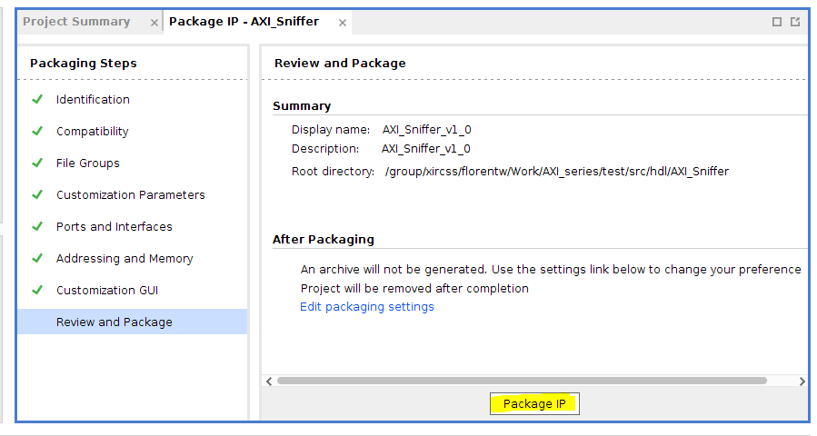
23. Click on the Review and Package section and click Package IP.
-
Remove the previous AXI_Sniffer IP from the BD of the initial project
-
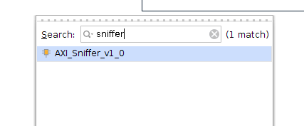
Right-click on the BD of the initial project and click add IP. Find the AXI Sniffer IP (which should have been automatically added to the IP catalog) and add it to the BD
- Try to connect the s_axi interface of our new AXI Sniffer IP to the bus between the AXI VIP and the AXI GPIO. This is now possible
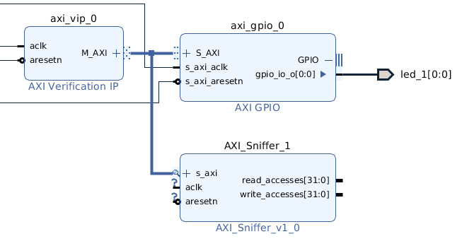
27. Connect the aclk and aresetn input port of the custom IP to the corresponding BD ports
- Validate the BD design. You should get no errors or critical warnings. Save the BD.
Finally, we can verify that our IP is working in simulation.
- Launch the simulation and add the port read_accesses and write_accesses of the AXI_Sniffer IP to the waveform window

30. Restart the simulation and run it for 3us

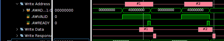
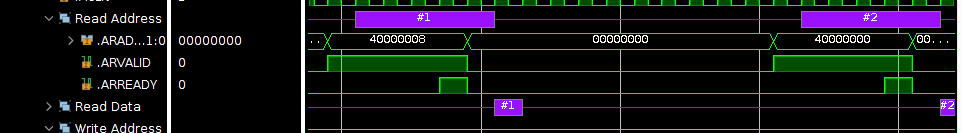
We can see in the simulation waveform that two write and two read transactions are happening. However our IP is counting only two write transactions and one read transaction
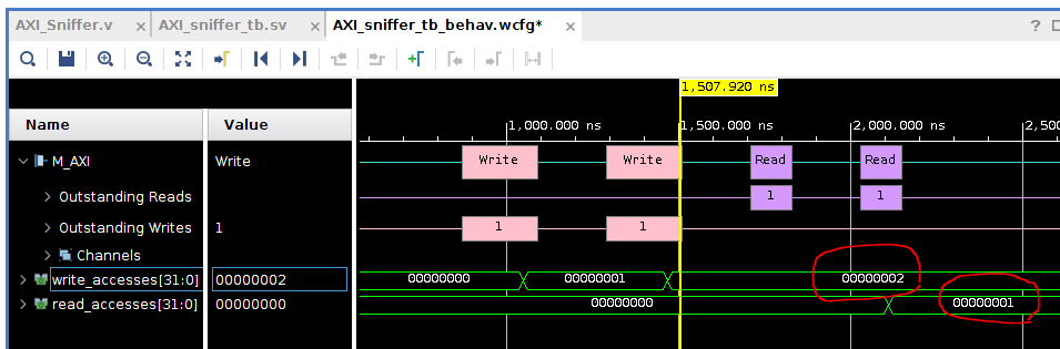
We can have a look at the addresses for each transaction to see if the output is correct. The two write transactions are happening at address 0x4000_0000 which is the address watched by the IP
However, only one read transaction is targeting the address 0x4000_0000 (the other reads 0x4000_0008) so the behavior of our IP is correct
This article shows only one example of what can be done with an AXI Sniffer (or monitor) IP. You can edit the Verilog code to add your own features.
Additional Learning
If you want to learn more about AXI, please see the other tutorials in this series: