https://support.xilinx.com/s/article/1137753?language=en_US
TITLE
AXI Basics 7 - Connecting to the PS using AXI4-Lite and Vitis HLS
AUTHOR
aoifem
LAST PUBLISHED DATE
10/12/2021, 8:39 AM
BODY
Introduction:
In AXI Basics 6 - Introduction to AXI4-Lite in Vitis HLS, we learned how to create an IP in HLS with an AXI4-Lite interface using C code. In this blog, we will learn how to export our IP so that we can use it in the Vivado Design Suite, how to connect it to other IP cores and a processor, and how to run our project on a board.
There are 3 sections to this blog:
-
Exporting our IP from Vitis HLS.
-
Create our hardware using the Vivado Design Suite.
-
Writing our software in the Vitis unified software platform, and running it on our board.
1. Exporting our IP:
In AXI Basics 6 - Introduction to AXI4-Lite in Vitis HLS, we created an IP core using the AXI4-Lite protocol. If we want to connect our new IP to any other IP, or to the PS, we first need to synthesize our software code into RTL (i.e. convert it into hardware). Then we can export our RTL IP to the Vivado Design Suite, where it can be connected to other IP cores or to the PS.
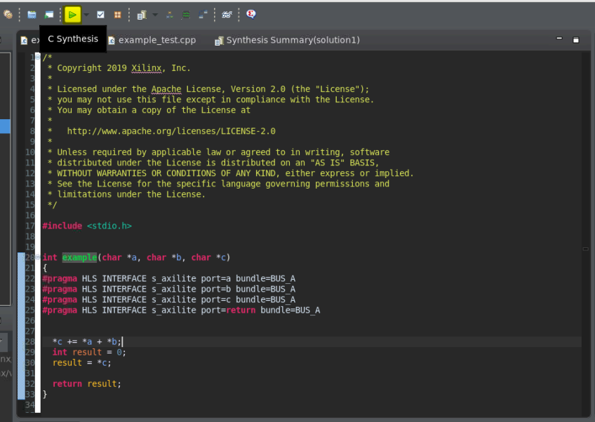
1.1 Edit the code as follows, and save it.
int example(char *a, char *b, char *c) { #pragma HLS INTERFACE s_axilite port=a bundle=BUS_A #pragma HLS INTERFACE s_axilite port=b bundle=BUS_A #pragma HLS INTERFACE s_axilite port=c bundle=BUS_A #pragma HLS INTERFACE s_axilite port=return bundle=BUS_A *c += *a + *b; int result = 0; result = *c; return result; }
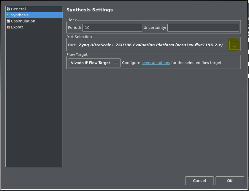
1.2. As we will be running this code on a board, we will need to change our synthesis settings to match the board we have available.
In my case, I chose the Zynq UltraScale+ ZCU106 Evaluation Board. To change the board go to Solution → Solution Settings → Synthesis Settings then Select the 3 dots highlighted below to select a board.
1.3. Run C synthesis by selecting the green ‘play’ button ![]() in the top of the screen. This will turn our code into RTL:
in the top of the screen. This will turn our code into RTL:
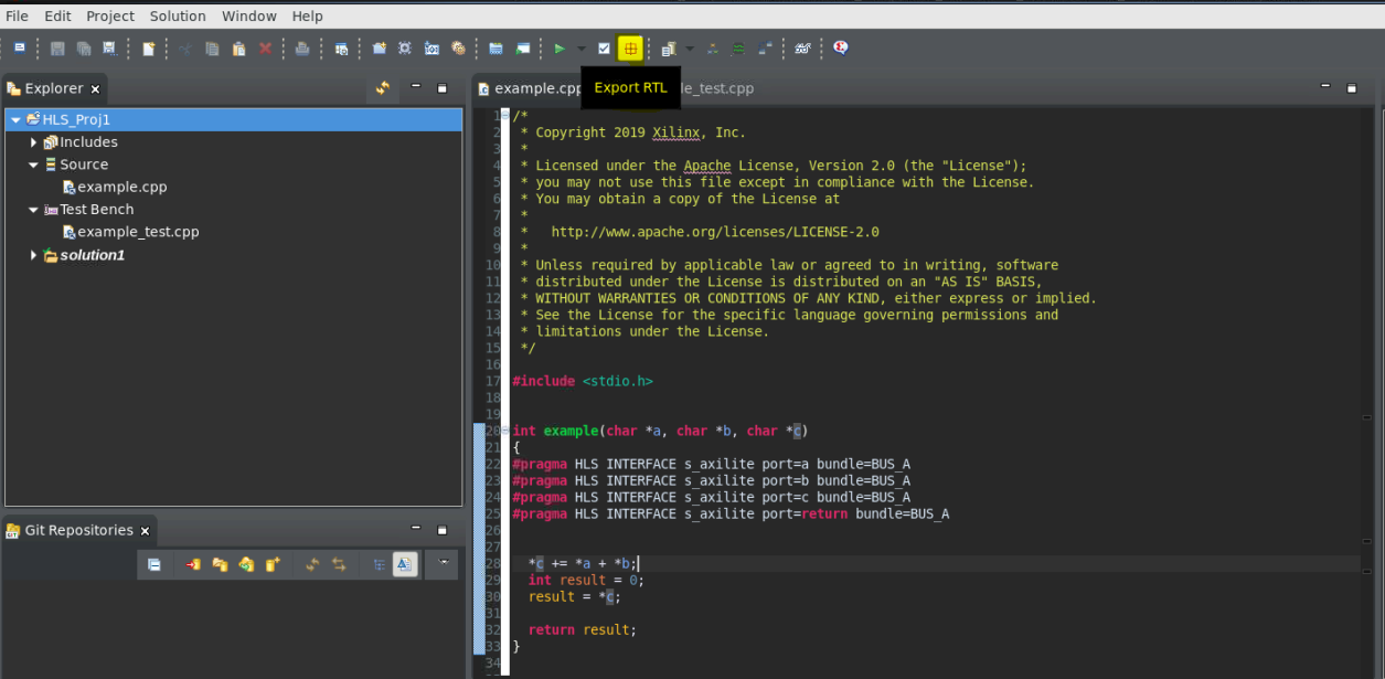
1.4. Once synthesis is complete, you can export the RTL by selecting the Export RTL toolbar button ![]() or click Solution → Export RTL to open the Export RTL dialog box.
or click Solution → Export RTL to open the Export RTL dialog box.
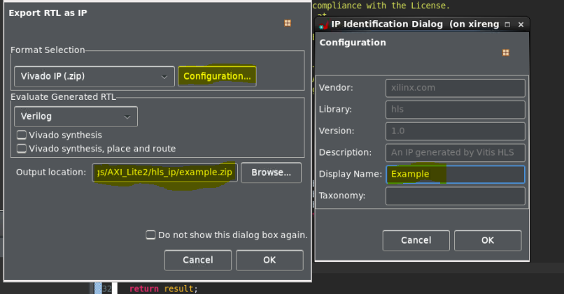
1.5. The dialog box should open as seen in the screen capture below.
This article contains a detailed explanation of all of the options available.
- Select the ‘configuration’ option to add details to your new RTL IP. Change the display name to ‘Example’, and select ‘OK’. This name will appear when you open your IP in Vivado Design Suite.
- Select the ‘Browse’ button to choose a location and a name for the outputted ‘Vivado IP (.zip)’ file. The outputted ZIP file will contain your RTL IP, which can be imported into Vivado Design Suite.
1.6. Wait for the tool to finish exporting, then open the Vivado Design Suite. Select the option to create a new project:
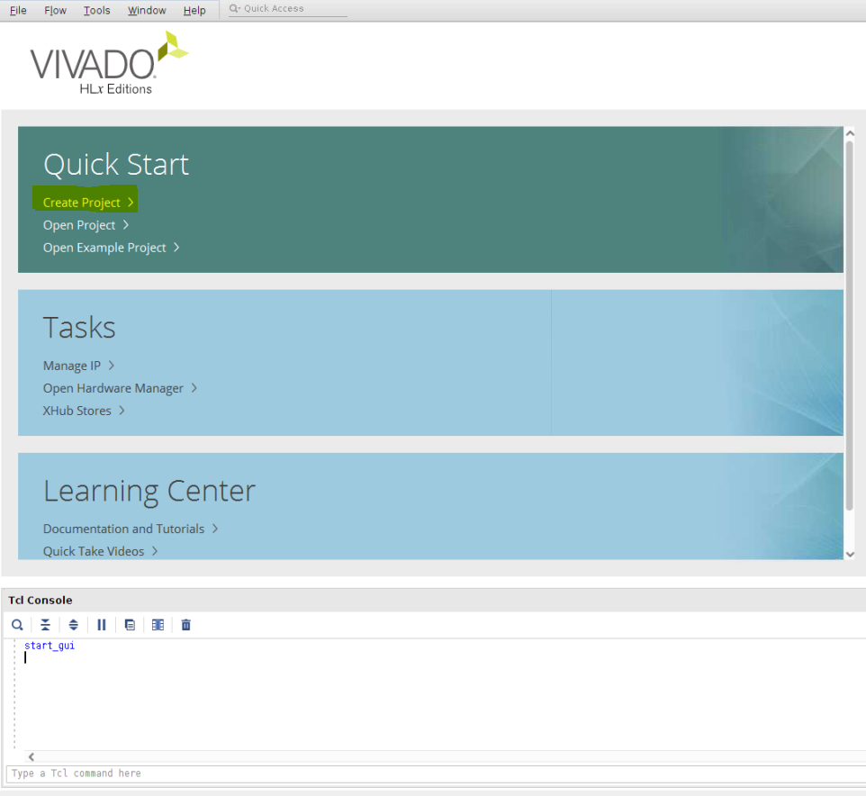
1.7. Select ‘Next’ through all of the options. When selecting the part, it is important to select the same part that you picked in Vitis HLS when you were creating your project. If you are unsure, the part selected can be found under solution settings → synthesis settings, in Vitis HLS. If you do not pick the same part, you might have problems importing your IP into the Vivado Design Suite.
Finally select ‘Finish’ to open an empty project.
1.8. To use the generated IP in a Vivado project, we first have to add your new IP repository to the Vivado project. This is the folder that contains the exported .zip file from Vitis HLS. To do this, select Settings → IP → Repository. Select the + button and select the location where you exported your IP in Vitis HLS (i.e step 6, above).
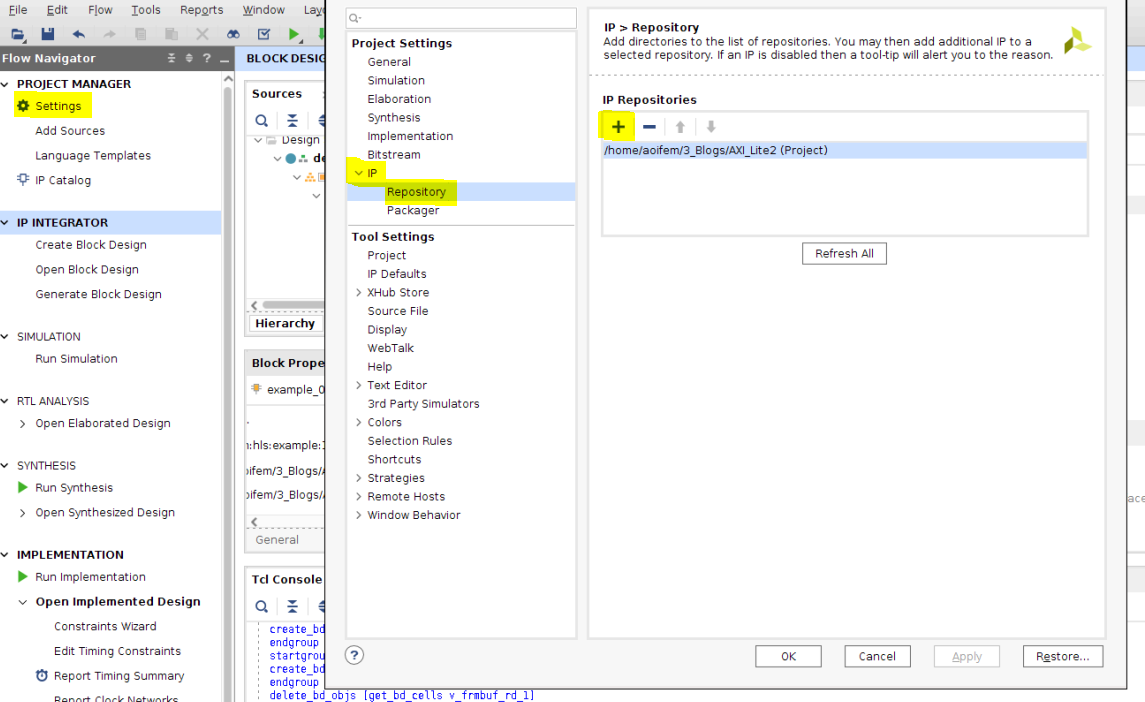
Select ‘Apply’ in the bottom of the dialog box, then select ‘OK’.
1.9. Select IP Catalog. You should now see your new Repository in the catalog.
If the IP was imported successfully, the number of IPs listed in the details window should now be ‘1’.
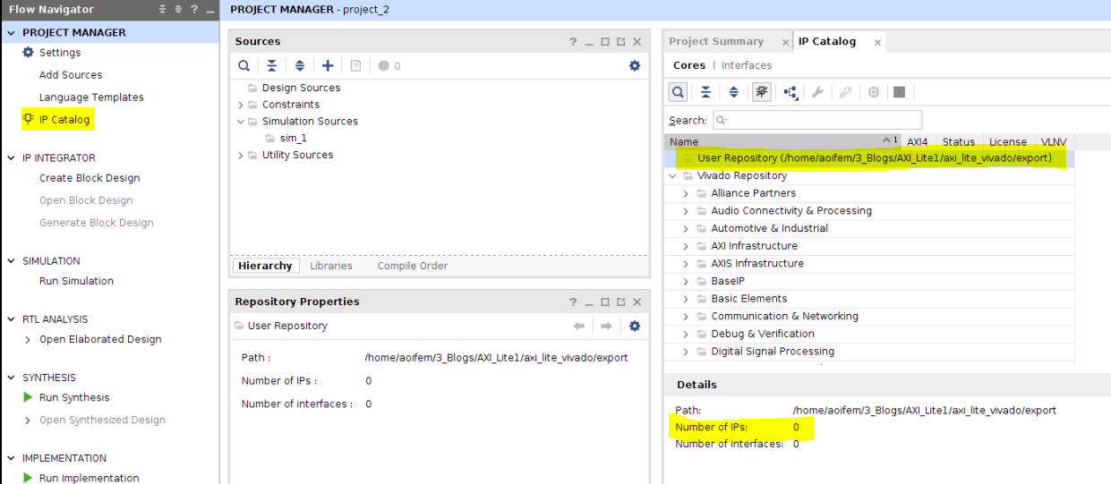
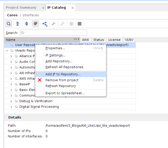
NOTE: If there are 0 IPs listed, you can right click on your new repository and select ‘Add IP to Repository’. Select the ZIP file you exported from Vitis HLS. You should then see the number of IPs in that repository as ‘1’. If not, double check the board/part you selected in Vitis HLS is the same as the one you are using in Vivado, otherwise, your IP may not be compatible.
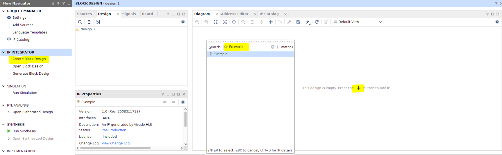
1.10. In the Flow Navigator, select ‘Create Block Diagram’.
In the resulting tab, select the + button and search for the name you gave your IP in Vitis HLS in Step 6 (i.e. Example).
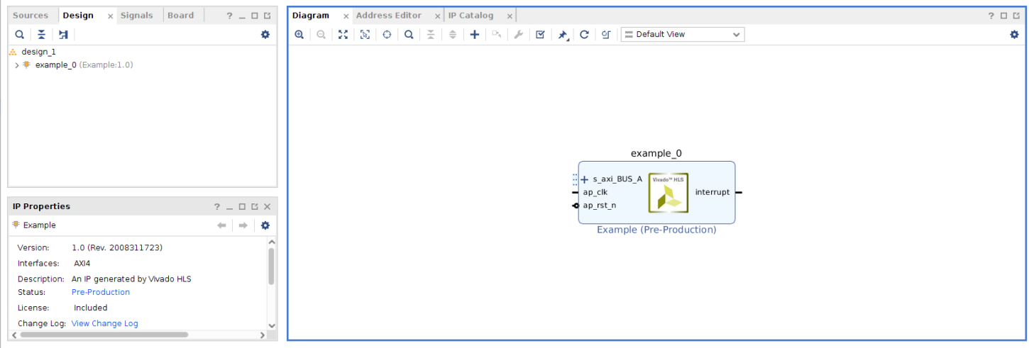
Congratulations! You have successfully created an IP, exported it from Vitis HLS and added it to a block diagram in the Vivado Design Suite.
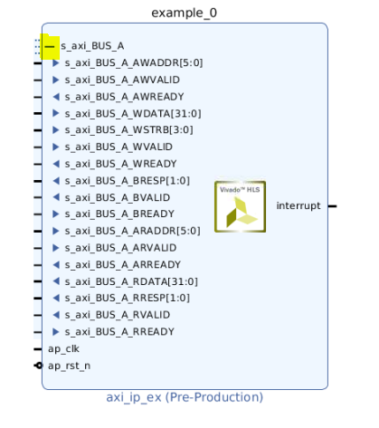
Clicking the + button beside s_axi_BUS_A shows a range of different ports. More information about these can be found in (PG155) under ‘Port Descriptions’.
Connecting to the PS:
2. Create your hardware:
You might want to connect to a PS in order to take advantage of its features. Adding a PS IP, such as the Zynq UltraScale+ MPSoC IP (available on the ZCU106 board), allows you to do this. More information about the Zynq UltraScale+ MPSoC IP can be found here.
2.1. Add the Zynq UltraScale+ MPSoC IP to your block diagram. Once added, a prompt should appear at the top of the screen. Select ‘Run Connection Automation’.
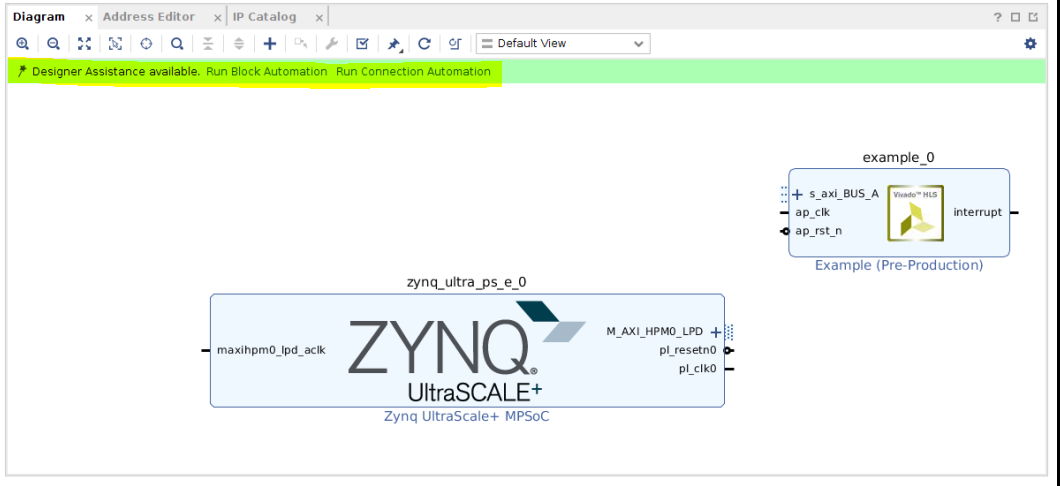
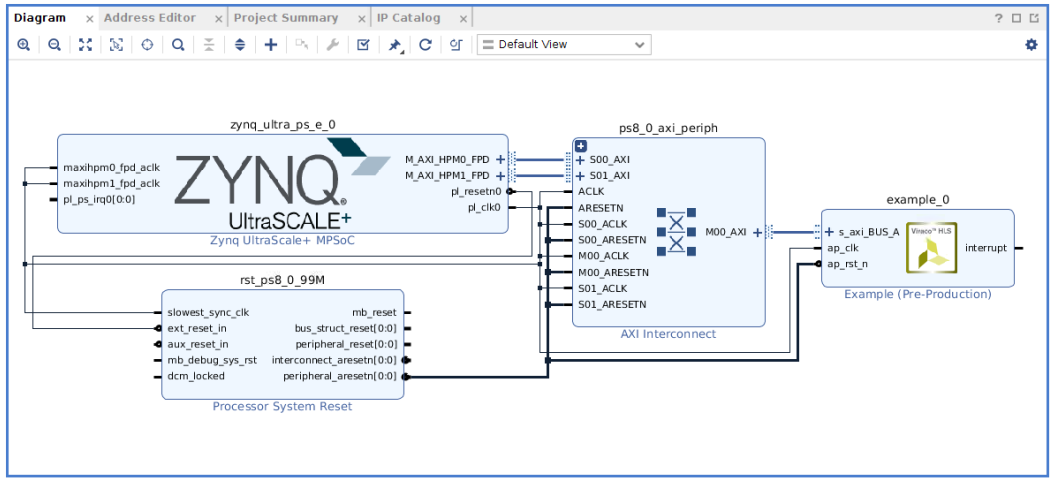
2.2. You should end up with the diagram below. Alternatively, you can add all of the parts for this IP manually and connect them as in the diagram. You should end up with the diagram below:
2.3. Create a HDL wrapper by right clicking on <design_name>.bd under the 'Sources’ tab. Run Synthesis then Implementation and Generate the bitstream. Next select File → Export → Export Hardware. Make sure to select the option to include bitstream, and take note of the selected export location. Doing this will create an XSA file, which contains all your hardware information. You can now close Vivado.
3. Writing your software
Now that your hardware has been created and exported, we need to write some software which tells our hardware what to do. We will be writing our software in Vitis. You will need to download the Vitis Core Development Kit from the Xilinx website.
3.1. Open Vitis. In the opening menu select ‘Create Platform Project’. This will be the base of our project, and we will add the hardware information (XSA file) and also write some software definitions here. Select the option to ‘create from XSA file’ when prompted. We then need to select the location of the exported XSA file, from section 2.3 above. Continue through the settings and click ‘Finish’ at the end.
3.2. Next we need to create an application project which will contain our software. This will be based on our platform project (so it will know our hardware information), and is needed to run an application on our target board. Select File → New → New Application Project.
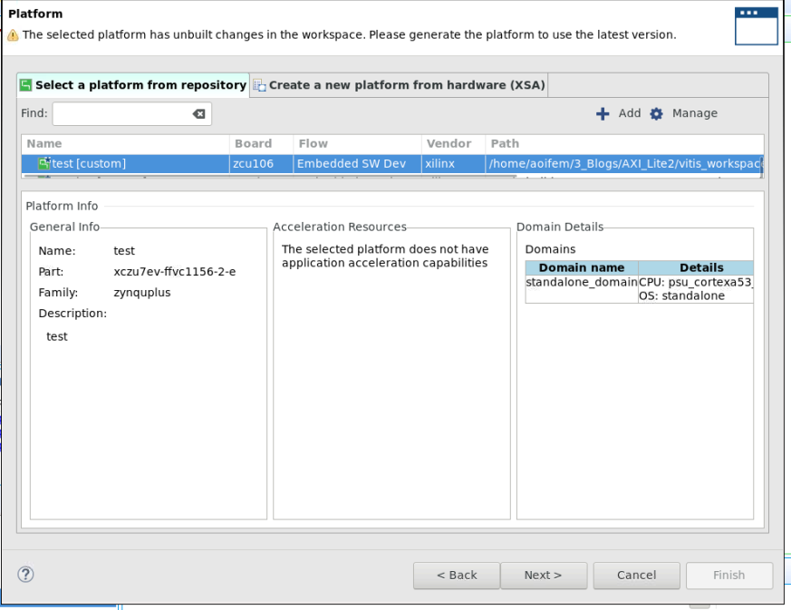
3.3. When prompted, select the option to Select a platform from a repository. Select the platform project created in step 3.1, then click ‘Next’.
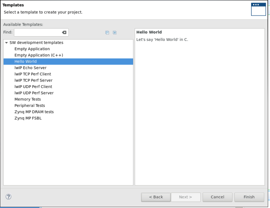
3.4 Select the Hello World Template and click ‘Finish’.
3.5. The Hello World code can now be seen under <application_project_name>/src/helloworld.c. As a sanity check, we are now going to download the example onto our board via the JTAG and read the printf statements using the UART.
To do this, connect your target board and open a terminal emulator software, such as Tera Term, to read the output messages. If you do not know how to do this, please reference your board’s user guide. Build and run the program. If done correctly, you should see the Hello World statement in Tera Term.
3.6. Now that we know our board is connected correctly, lets create some code which uses our HLS IP. Copy the code from Vitis_Code.c (attached to this tutorial), and paste it into helloworld.c, replacing the original helloworld code.
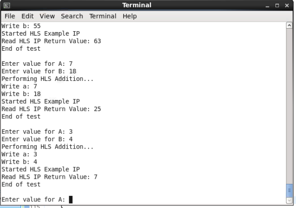
Save, build and run the software again. This time in Tera Term you will be asked for two inputs, A and B. These will be the inputs to your HLS IP, which will be added together and the result will be displayed.
Note: As A and B were defined as type ‘char’ in Vitis HLS, only values up to 127 should be entered.
The sample code uses functions which are automatically created by Vitis, which makes development very quick and easy.
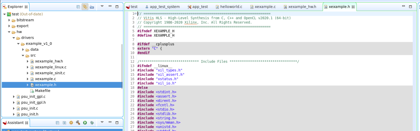
The functions used can be found in a file called X<HLS_IP_name>.h, and can be found under <platform_project>/hw/drivers/<ex_name>/src. The functions are explained in detail here. Take a look at this file, and the other related files in this folder. These can be edited to further control your IP, program the interrupt etc.
Additional Learning:
Congratulations! You have now created your own IP in Vitis HLS with an axilite interface, and connected it to the PS. If you want to learn more about AXI, please see the other tutorials in this series:
| Link | Description |
|---|---|
| AXI Basics 1 - Introduction to AXI | This blog entry will cover some of the basics of AXI3/AXI4 on Xilinx devices. First we will start with the less exciting parts, the theory and the terminology. |
| AXI-Basics-2-Simulating-AXI-interfaces-with-the-AXI-Verification | The Xilinx AXI Verification IP (AXI VIP) is an IP which allows the users to simulate AXI4 and AXI4-Lite. It can also be used as a AXI protocol checker. |
| AXI-Basics-3-Master-AXI4-Lite-simulation-with-the-AXI-VIP | In this new entry we will see how we can add an AXI VIP into a Vivado project to simulate an AXI4-Lite interface. We will then look at the signals used for AXI4-Lite transactions in the simulation waveform window. |
| AXI-Basics-4-Using-the-AXI-VIP-as-protocol-checker-for-an-AXI4-Master-Interface | In this article we will see how we can use it to validate (and find errors) in an AXI4 (Full) Master interface. |
| AXI-Basics-5-Create-an-AXI4-Lite-Sniffer-IP-to-use-in-Xilinx-Vivado-IP-Integrator | In this article I will show you how to create a basic AXI4-Lite sniffer IP which will count the read/write transactions happening at a specific address. |
| AXI Basics 6 - Introduction to AXI4-Lite in Vitis HLS | In this article we will explore the basics of how to create a custom IP with an AXI4-Lite interface in Vitis HLS. |
| AXI Basics 7 - Connecting to the PS using AXI4-Lite and Vitis HLS | In this article, we will learn how to export our IP so that we can use it in the Vivado Design Suite, and how to connect it to other IP cores and a processor. |